Aleph Setup
Unbox and setup your Aleph Flight Computer for development
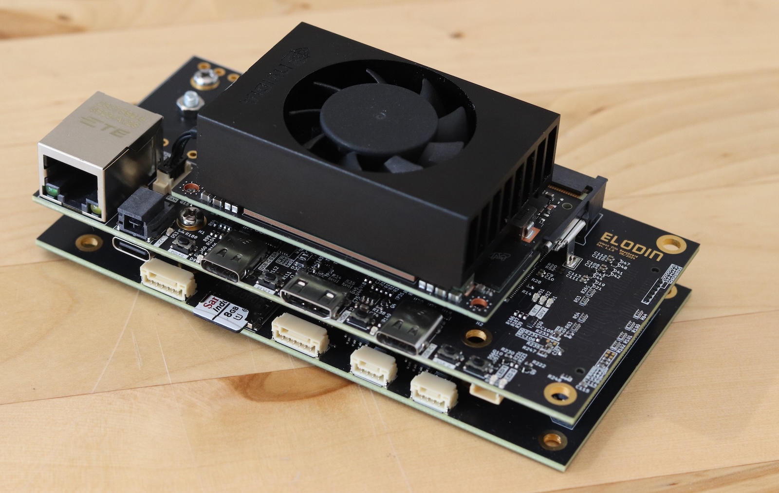
Thanks for purchasing an Aleph Flight Computer! This guide will help you get started with your new device. We'll cover:
- Turning on and connecting to Aleph via (USB) serial or SSH
- General development workflow such as flashing custom firmware
- Accessing sensor data from the compute environment
For more detailed information on the hardware (including pinouts, sensor suite, connectors, etc.), please refer to the ES01 datasheet.
Unboxing & Assembly
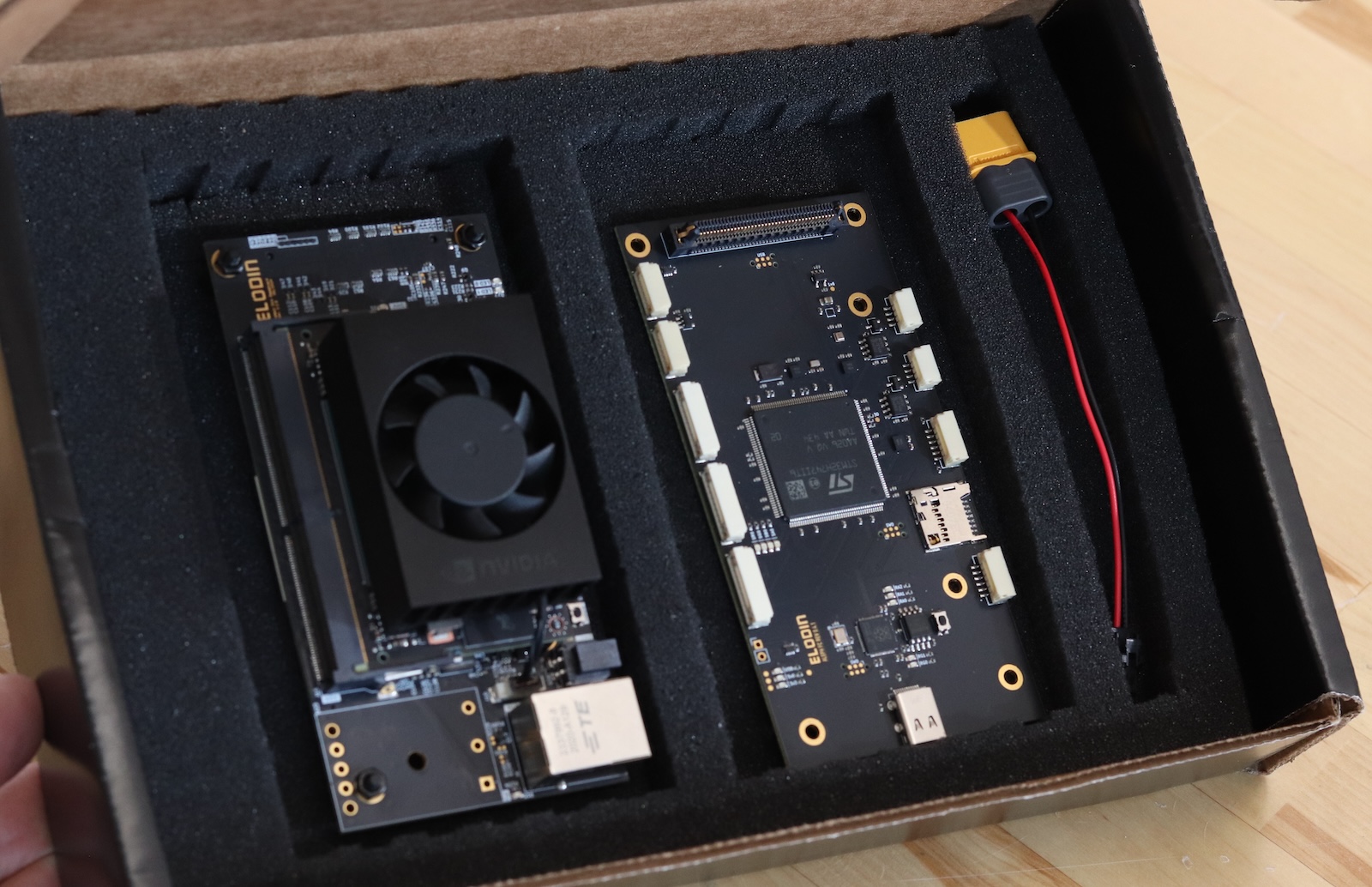
Inside the box you'll find (from left to right):
- The Aleph "carrier board", an AI-capable computer including a pre-mounted Nvidia Orin NX SoM
- The Aleph "flight controller (FC) board", an open-source flight controller based on the STM32H747 microcontroller
- An XT60 to Molex Nano-Fit power cable for connecting a 4S LiPo battery
Aleph requires 12-18V DC power (minimum 30W) to operate. Do not connect a battery or any other power source exceeding 18V.
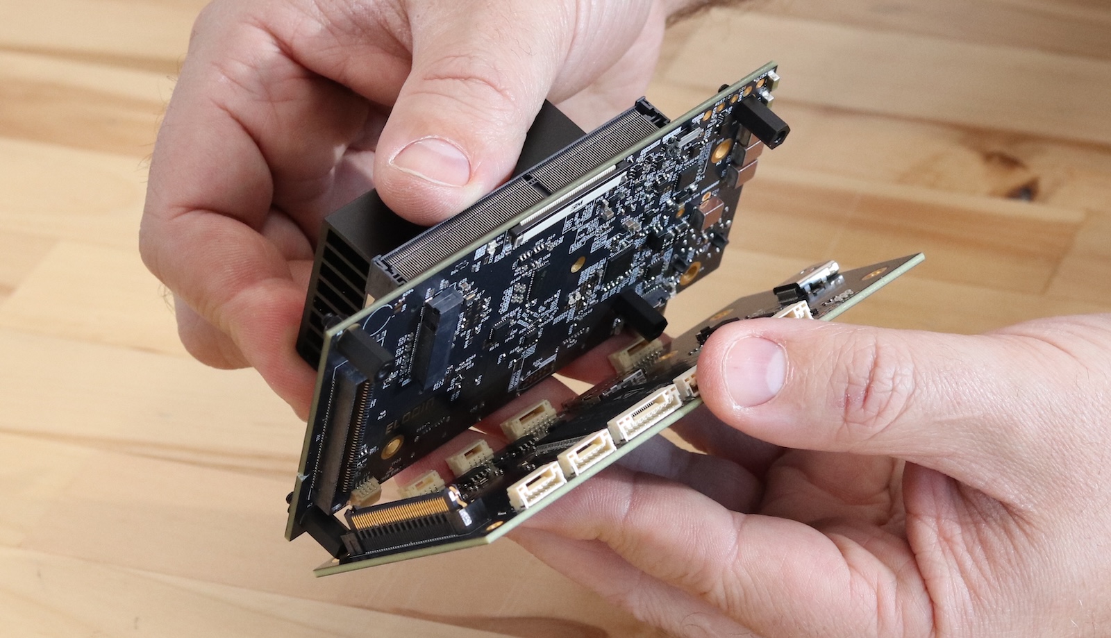
Let's go ahead and stack the boards. Align the board-to-board connector and gently press the boards together. The boards should be flush with each other. Use the provided screws to secure the boards together via the pre-mounted standoffs.
Powering On
Both the carrier and FC boards come with software pre-installed. During normal development, you'll use 2 USB-C cables: one to power the board, and the other to connect to your laptop:
- Connect "USB-C Power" to a 30W+ USB-PD power supply.
- Either:
- Connect "USB-C w/ Serial" to your laptop for serial console access.
- OR Connect "USB-C w/ Ethernet" to your laptop for an ethernet connection to the carrier board, allowing SSH access
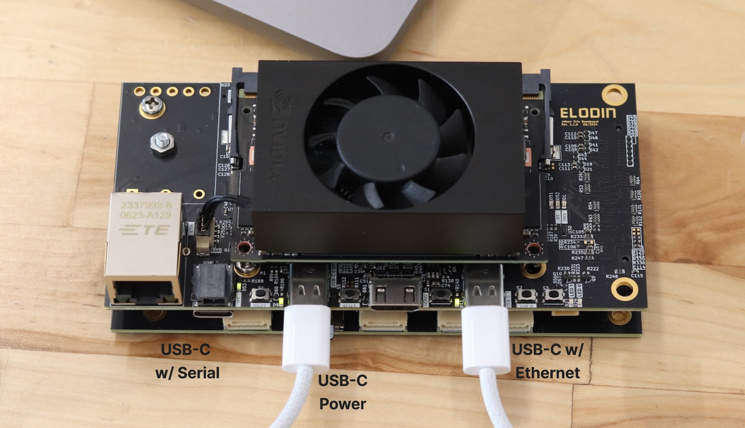
Go ahead and connect your USB-C cables now. Aleph will power on automatically when connected to power. If the fan doesn't spin, it may be in manual mode. There is a switch on the underside of the carrier board to toggle between manual and automatic power-on. Toggle to automatic and reconnect the power.
Not all high wattage USB-C power supplies support USB-PD. For example, some USB-C laptop chargers provide 50W+ but use a proprietary protocol incompatible with USB-PD. Make sure to use a USB-C power supply that explicitly advertises USB-PD support. You can also use a lab power supply set to 12-18V DC (minimum 30W).
Make sure to connect the power cable first. Otherwise, the laptop will attempt to power the board over the data cable, but it cannot provide enough wattage for the Orin module to boot successfully. This will cause the board to power cycle repeatedly.
Connecting via Serial USB
You can connect to Aleph and observe the boot process by connecting a USB-C cable to the carrier board's USB-C port labeled "Serial". Once connected, open a terminal and run the following command to observe the boot process:
Linux/macOS
# find the newly connected USB serial device
# connect to the device (for example)
Sometimes, such as on Ubuntu you may need to grant permissions to the device before connecting with
screen, i.e. sudo chmod 666 /dev/ttyUSB0
Windows
# find the newly connected USB serial device
# open device manager and look for the new COM port
# connect to the device (for example)
After booting completes, you should see the login prompt. You can log in with the default credentials:
- Username:
root - Password:
root
Aleph ships with root access enabled by default. We recommend disabling root access and enabling passwordless SSH keys for security.
Accessing Sensor Data
Aleph has a variety of sensors available for use in your applications. You can access the sensor data from the compute environment by running the following commands in your terminal:
# terminal 1
# terminal 2
# terminal 3
This data is also written to the provided SD card on the FC board. See Develop Firmware for FC Board section below.
Connecting via SSH / Ethernet USB
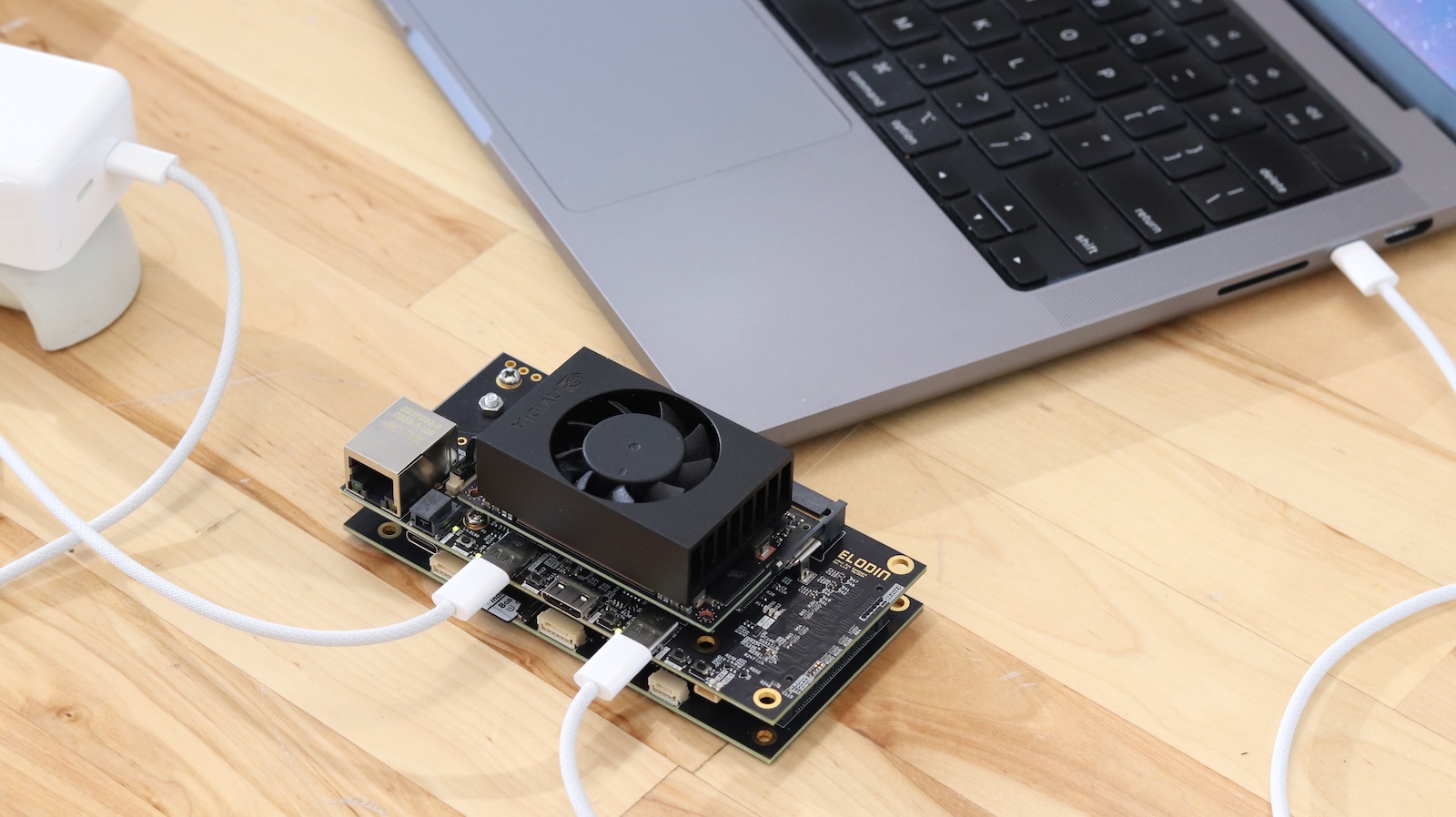
After connecting the USB-C cable to the carrier board's USB-C port labeled "Ethernet", you can connect to the carrier board via SSH.
You can check for a successful connection by running this command in your terminal and looking for the Aleph's IP address:
|
Wait approximately 30 seconds for the carrier board to boot up before attempting to connect via SSH.
The Aleph connection will be a new local network connection broadcasting as aleph.local.
The carrier board runs a custom Linux distribution with a pre-installed SSH server. You can connect to the carrier board via SSH using the following command:
Sometimes the device will connect as an unresolved IP address at a 169.254.x.x address. If this happens, you can connect to the device by
manually updating the DHCP settings on your computer to use a static IP address of 10.224.0.2 with this device instead. The device server
will be at 10.224.0.1
Development Workflows
Software development for Aleph consists of:
- Developing OS updates for the carrier board
- Developing AI/ML workloads for the carrier board
- Developing firmware for the FC board
Developing OS Updates for the Carrier Board
Coming Soon
Develop AI/ML Workloads for Carrier Board
Coming Soon
Develop Firmware for FC Board
The FC board has a built-in RP2040-based programmer that is pre-flashed with debugprobe firmware that allows it to function as a CMSIS-DAP probe. This makes it easy to flash new firmware onto the FC board over USB using standard tools such as OpenOCD or probe-rs. We recommend using probe-rs because it has less of a configuration burden, and has out-of-the-box support for RTT (Real-Time Transfer) logging.
Probe-rs v0.25.0 has a regression that prevents it from working well with the STM32H7 series. We recommend using v0.24.0 until the issue is resolved.
Install probe-rs v0.24.0 using the following install scripts:
Linux/macOS
|
Windows
|
Clone the elodin repository and navigate to the fsw directory:
The fsw directory contains several example projects, navigate into the multicopter directory & follow the build instructions there. The
last step is the command cargo rrb fw, which will build the firmware and flash it to the FC board. You should see the same sensor output as before
when connected to the Base Board, or alternatively can follow the instructions in the multicopter directory readme to collect sensor data
from the included SD card.
Reset to Factory Settings
Carrier Board
The following steps will reset the carrier board to a known good state with the default firmware and OS image that was shipped with the device. This process is not required for typical iterative development, but can be useful if you encounter issues with the carrier board or if you want to update the Linux kernel.
Pre-requisites
- Acquire a laptop or desktop computer running Ubuntu 24.04 LTS, with at least 100GB in storage space available.
- Install the following dependencies:
- Install determinate nix and open a new terminal session.
A new terminal session is required after installing Nix because it needs to set up environment variables and shell configurations that are only loaded during terminal initialization. This ensures the Nix package manager is properly added to your system PATH and all Nix-related commands become available.
- Disable automatic mounting of external storage devices.
Automatic mounting can interfere with the flashing process because the device needs to be accessed directly for programming/flashing purposes. This can be re-enabled after the flashing process is complete.
Build and Flash
- Clone the elodin repository with
git clone https://github.com/elodin-sys/elodin.git. - Navigate to the aleph image build folder with
cd elodin/images/aleph. - Run
nix build .#initrd_flashto build the carrier board's OS image, firmware, and flashing script.
This build can take a very long time, over an hour. You'll see a build progress bar similar to this:
[10/428/617 built, 953 copied (10910.1 MiB), 2826.5 MiB DL]
Which refers to packages building now / built / total to be built
- Connect your Aleph carrier board to USB-C power, and connect the USB-C Ethernet port to your computer.
- Hold the "RECOV" button, press and release the "RESET", release the "RECOV" button to enter recovery mode.
- Run
lsusbin your terminal and confirm that a device named "NVIDIA ... APX" is present.
|
- Run the flashing script:
sudo result/bin/initrd-flash-aleph. - You should see a successful flash message, and the carrier board will reboot into the new OS image.
- Connect via the USB-C serial port and test as described above.
FC Board RP2040 Debugger
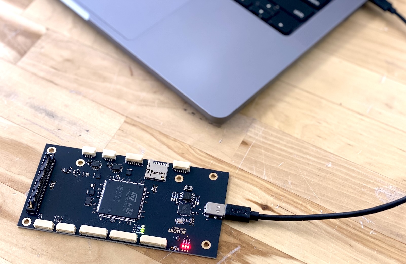
This is easiest to perform when separated from the stack to provide access to the bootloader button.
- While pressing the bootloader button, connect Aleph FC to your computer and confirm that all 3 red power LEDs (labelled “USB”, “5v0”, and “3v3”) are on.
- Your computer should recognize a new drive labeled "RPI-RP2".
- Download the debugger UF2 firmware file here.
- Drag and drop the UF2 firmware file onto the "RPI-RP2" drive. This flashes the necessary firmware onto the built-in debugger, and resets the board. Confirm that the “RG0” green LED is now on.
- Continue to re-flash the firmware as needed using the development process described above.
Betaflight
Aleph FC is compatible with Betaflight firmware.
Betaflight Installation
Download the patched Betaflight firmware here
the Betaflight patches needed to support Aleph are trivial and open source.
Flash the Betaflight firmware using the following command:
Keep Aleph FC plugged into your computer, and visit app.betaflight.com.
The Betaflight web app requires a Chromium-based browser (Chrome, Chromium, Edge) because it uses Web Serial API, which is not well supported on other browsers.
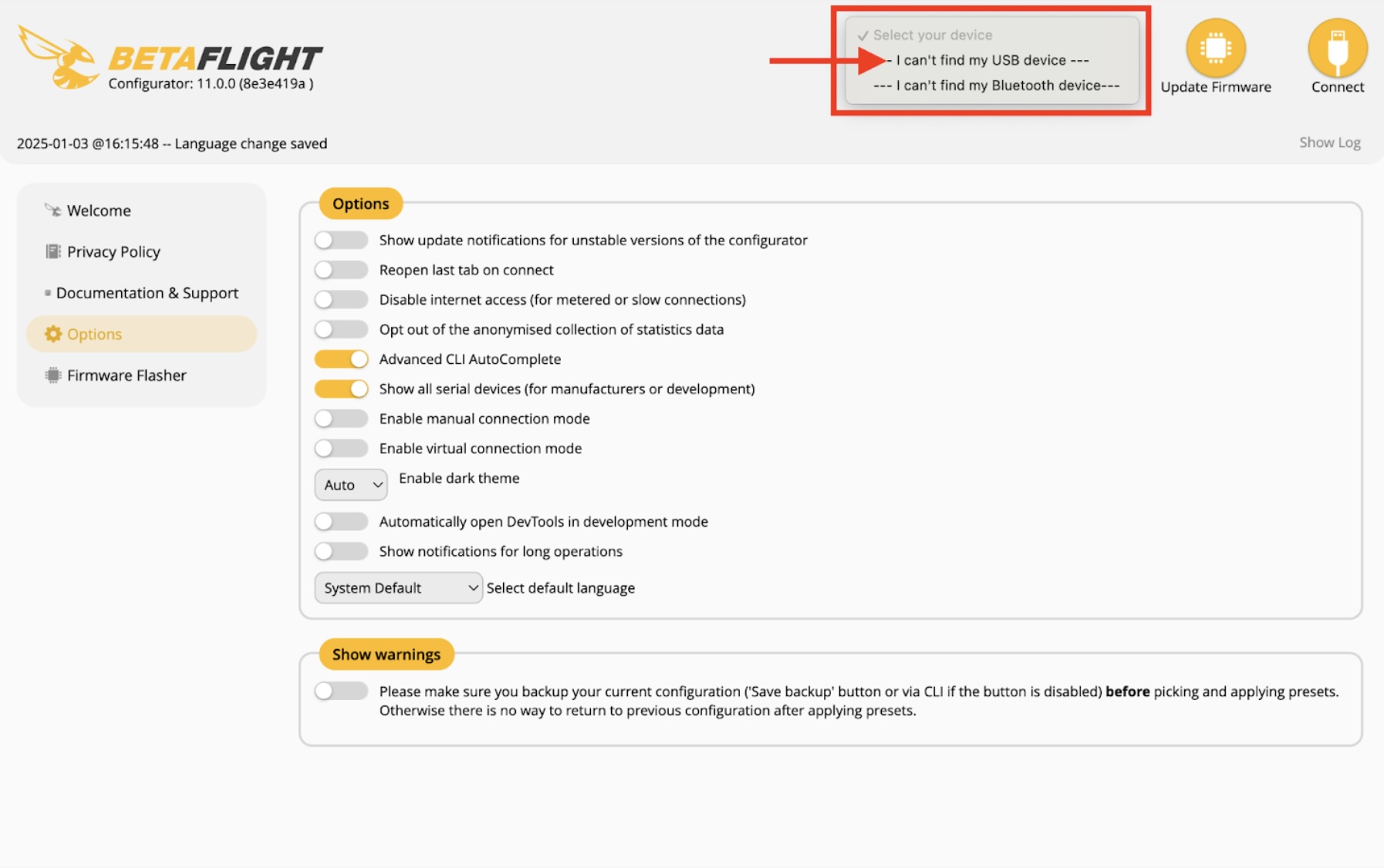
Go to the Options tab and enable the Show all serial devices option.
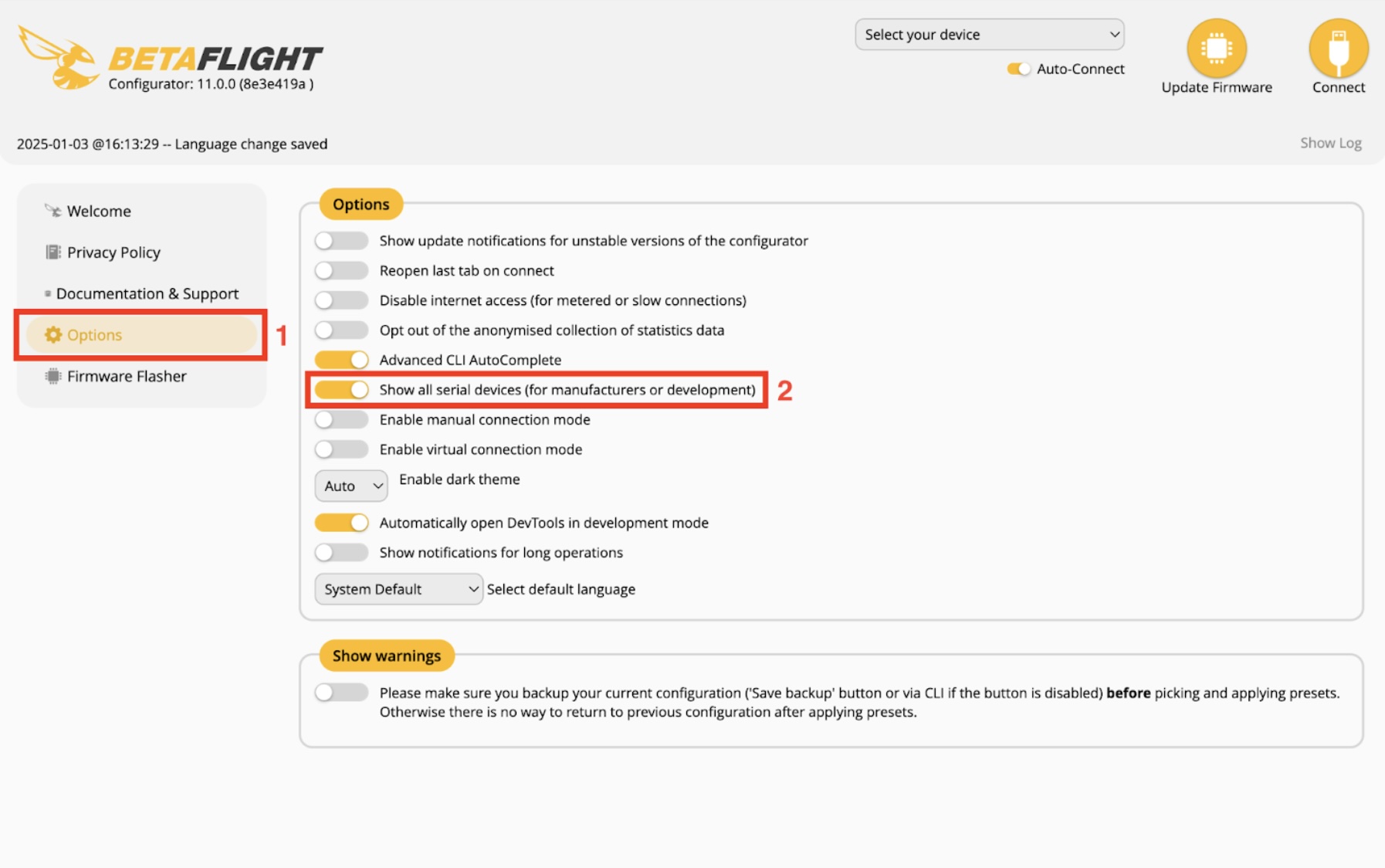
Click on Select your device in the top-right corner, and choose I can’t find my USB device.
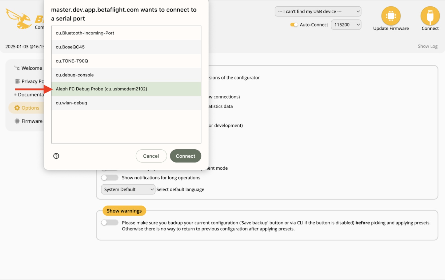
Choose Aleph FC Debug Probe from the list of serial port devices and click on Connect.
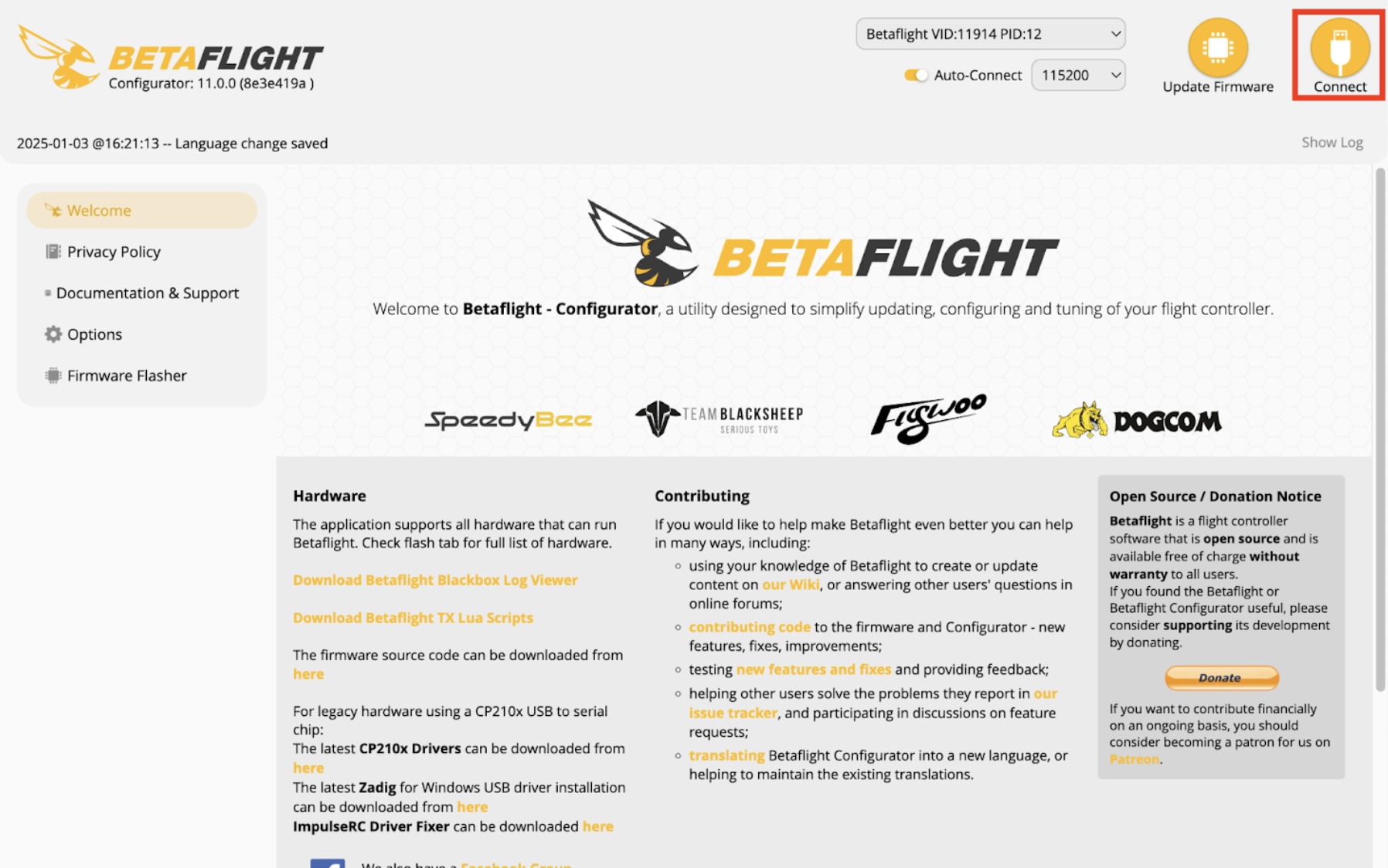
In some cases, you may have to click Connect again in the top-right corner to connect to the FC.
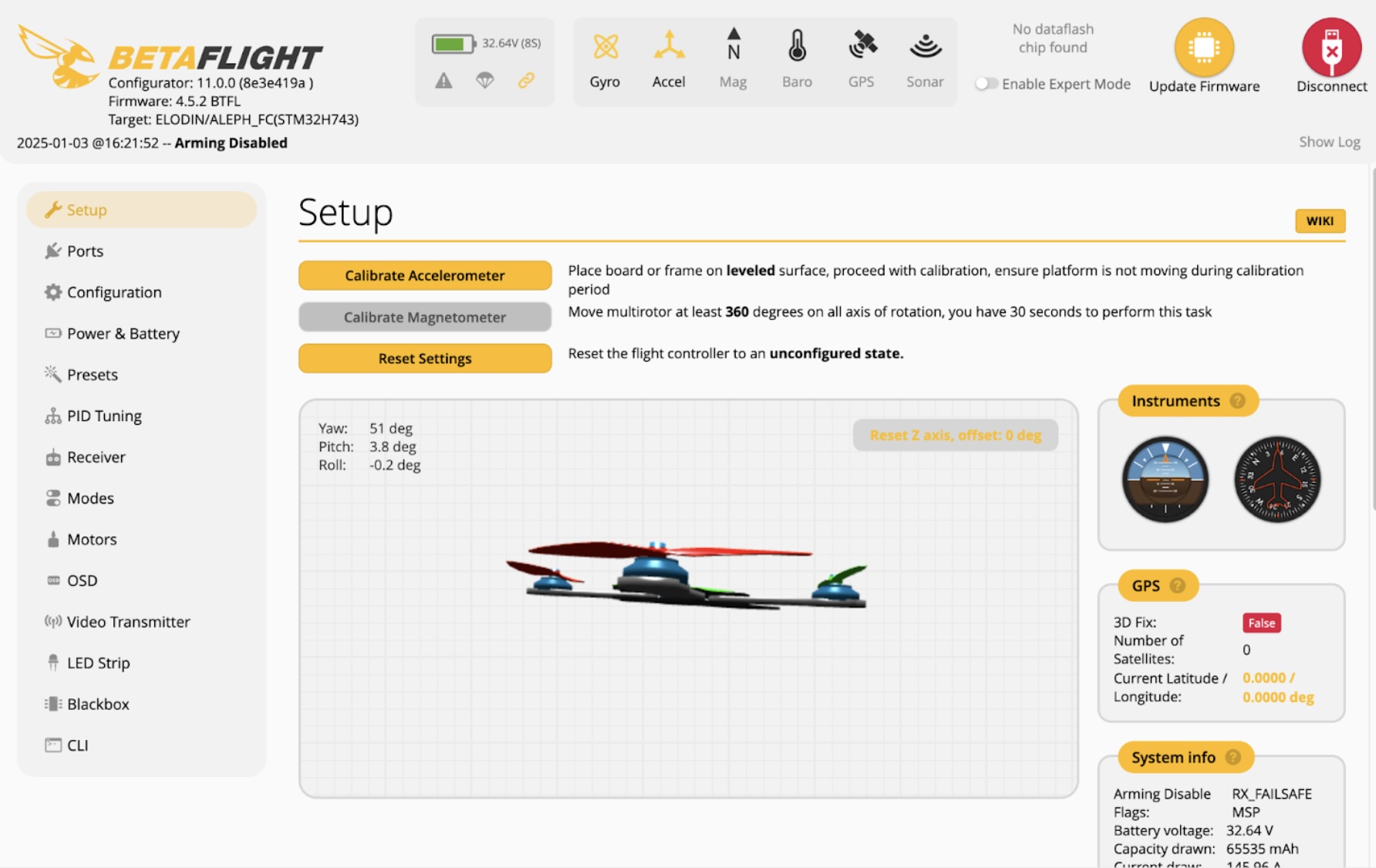
The betaflight configurator should now be fully connected to the FC.
Reference Quadcopter Design
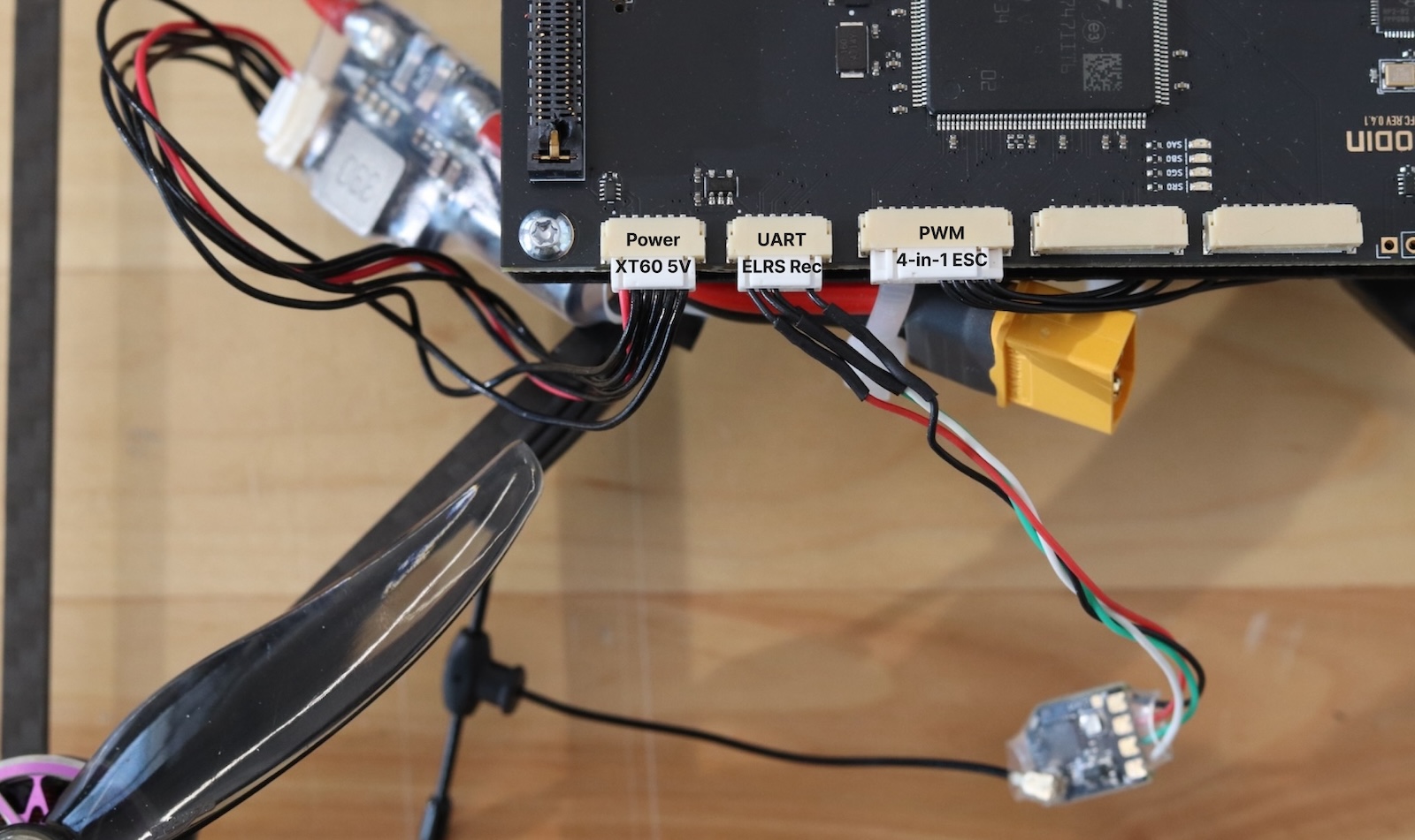
We've tested Aleph FC with Betaflight on a 7" quadcopter design.
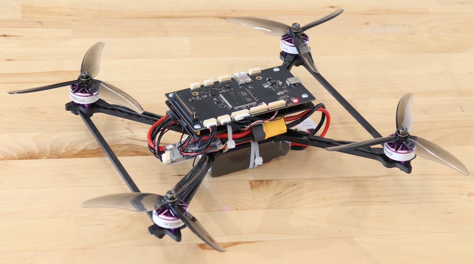
If you'd like to replicate our quadcopter design, the shopping list includes:
- 4x V2306 V3.0 KV1750 motors link
- Generic 1300 mAh 3S Battery link
- Generic 7" Carbon Fiber Frame link
- Generic 3-blade propellers link
- RadioMaster Pocket ELRS controller link
- RadioMaster ELRS receiver link
- XT60 pass-through power module link
- Generic 4-in-1 30x30 ESC link
